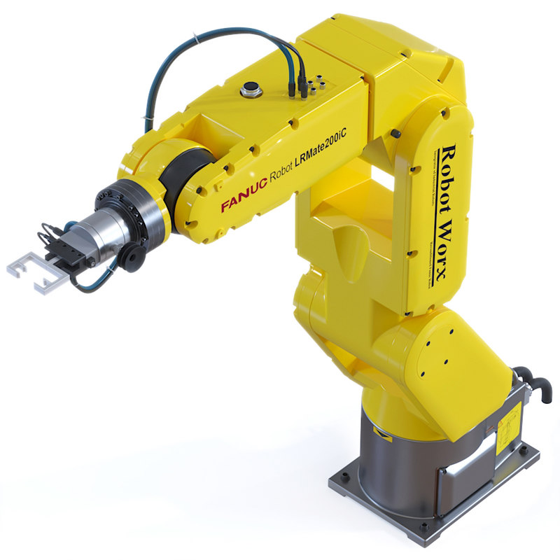
- Download Fanuc 3D Models for 3ds Max, Maya, Cinema 4D, Lightwave, Softimage, Blender and other 3D modeling and animation software. 3D CAD BROWSER. Fanuc 430 Robot [CAD] Fanuc 710 Robot [CAD] Fanuc LR Mate Robot; Fanuc M10ia Robot Arm 6-Axis [CAD] Fanuc M16ib - AM120iB; Fanuc M20iA [CAD] Fanuc M-410iB [CAD].
- Robot CAD CAM solutions from Global Robots. In the past it has been very expensive and complex to convert CAD files into robot movements. Part of the problem has been that such systems were only possible using the latest machines often with a lot of optional extras. Another problem has been the cost of the software.

Fanuc Robot Models Downloads
I am new to both SolidWorks and RobotWorks, and while I am inthe initial stages of learning them, I am interested inestablishing a protocol for dealing with the different coordinatesystems presented by robotics (Z+ points up from the top plane) andCAD (Z+ points out from the front plane).
I am using RobotWorks 5 and SW 2009 for OLP (Off LineProgramming)applications for my Fanuc ArcMate 100i w/ a J2controller and I plan to build a library of apps for the robot torun. A functional hurdle I am experiencing is that since robots seez+ as up, when you add robot stuff to your assembly SW lays yourmodel(s) on thier side (z+ faces out in SW).
I discovered the way to make the SW views display the environmentfrom a robotics point of view; by modifying the view(s)orientation, but that only sets the views and does not change theactual coordinate system.
My hope is to formulate a protocol to be able to create a workcellfor the robot; bring parts to it from a variety of sources andvirtually set the robot to work on them.
That said, the simplest way seems to be to: build the workcell andall parts except the robot in SW, bring the robot in and mate it tothe workcell. The potential problems I see are related to therobot's coordinate systems and user frames once you have flopped itdown (upright).
I am wondering if anyone has worked thru this hurdle anddiscovered anything problematic about changing a robot's coordinateorientation?
Would it be better to accomodate the robot and always flip the CADcoordinate system in my mind to accomodate the robot's coordinatesystem? Yikes! This would make the front plane the top, the topplane the back... etc. each time I design or import a model...using the view orientation change mentioned above would facilitatevisualiing this 'flip'... But I would need to do it each time I ...and... yea... that's why I'm asking:
Has anyone worked thru this hurdle and come up with a plan?
Solidworks Models Of Fanuc Robots For Sale
RobotWorks is a robotics CAD that runs with SOLIDWORKS on a Windows PC. Use RobotWorks for workcell design, motion simulation and robot programming inside one interactive CAD environment. RobotWorks uses the SOLIDWORKS graphics and internal engine to create a robot path quickly along faces, edges and curves of CAD objects. The following robot types are currently modelled and available in EASY-ROB™. If your robot is not in the list we can create it upon request. Download EASY-ROB™ Fanuc Robot Library with EASY-ROB™ Viewer. Whether you are a first time buyer or experienced in automation, our sales representatives and robot technicians can help you choose the right industrial robot to meet your application requirements. FANUC Robots.